
Fiber optic connector
1. Transmission mode
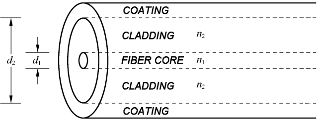
Refers to the transmission mode of light in optical fibers (electromagnetic field distribution form). The commonly used communication fiber
modes are divided into single mode and multimode, with single mode suitable for long-distance transmission and multimode suitable for
short-range transmission. G652D single mode optical fibers have a core diameter d1 of 9 um and a cladding diameter d2 of 125 um. Multimode
optical fibers are commonly divided into two forms: 62.5/125 or 50/125.
The selection of optical fiber mode must match the optical module, otherwise it will cause additional losses due to core diameter mismatch.
Interconnection between optical fibers and cables with different core diameters is not recommended.
2. Insertion loss
The amount of optical signal power reduction, usually expressed in decibels, when using fiber optic connectors for connections. For example,
when the insertion loss is 3dB, the optical power loss is approximately 50%. When the insertion loss is 1dB, the power loss is approximately
20%, and IL=- 10lg (output optical power/input optical power).
3. Return loss
Also known as reflection loss, it refers to a parameter of the signal’s reflection performance. Echo loss describes the amount returned by the
optical signal when it returns to the original path. Generally, the larger the value, the better. For example, when input 1mw power, 10% of it is
reflected back, which is 10dB, and 0.003% is reflected back, resulting in an echo loss of approximately 45dB. RL=- 10lg (reflected light power/
input light power)
4. Face type
Optical fiber surface types are divided into PC (spherical surface grinding) and APC (oblique spherical surface grinding). After APC grinding,
the reflected light beam returning along the original path is greatly reduced, which helps to improve the return loss of the connector
Post time: Apr-03-2023