
The main electrical connection mainly refers to the circuit that is designed to meet the predetermined power transmission and operation
requirements in power plants, substations and power systems, and indicates the interconnection relationship between high-voltage electrical
equipment. The main electrical connection is an electric energy transmission and distribution circuit with the incoming and outgoing lines
of the power supply as the basic link and the bus as the intermediate link.
In general, the main wiring of power plants and substations shall meet the following basic requirements:
1) Ensure the necessary power supply reliability and power quality according to the requirements of the system and users. The less chance
of forced interruption of power supply during operation, the higher the reliability of main wiring.
2) The main wiring shall be flexible to meet the requirements of various operating conditions of the power system and main equipment, and
shall also be convenient for maintenance.
3) The main wiring shall be simple and clear, and the operation shall be convenient, so as to minimize the operation steps required for the
input or removal of main components.
4) Under the condition of meeting the above requirements, the investment and operation costs are the least.
5) Possibility of expansion.
When there are many incoming and outgoing lines (more than 4 circuits), in order to facilitate the collection and distribution of electric energy,
the bus is often set as an intermediate link.
Including: single bus connection, double bus connection, 3/2 connection, 4/3 connection, transformer bus group connection.
When the number of incoming and outgoing lines is small (less than or equal to 4 circuits), in order to save investment, no bus can be set.
Including: unit wiring, bridge wiring and angle wiring.
1、 Single bus connection
The connection with only one group of buses is called single bus connection, as shown in Figure 1.
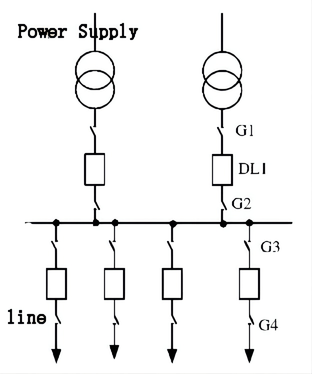
Fig. 1 Schematic diagram of single bus connection
The characteristic of single bus connection is that the power supply and power supply lines are connected on the same group of buses. In
order to switch on or cut off any incoming or outgoing line, each lead is equipped with a circuit breaker that can open or close the circuit
under various operating conditions (as shown in DL1 in Figure 1). When it is necessary to maintain the circuit breaker and ensure the
normal power supply of other lines, isolating switches (G1 ~ G4) shall be installed on both sides of each circuit breaker. The function of the
disconnector is to ensure that the circuit breaker is isolated from other live parts during maintenance, but not to cut off the current in the
circuit. As the circuit breaker has an arc extinguishing device, but the disconnector does not, the disconnector should follow the principle of
“make before break” during operation: when connecting the circuit, the disconnector should be closed first; Then close the circuit breaker;
When disconnecting the circuit, the circuit breaker shall be disconnected first, and then the disconnector. In addition, the disconnector can
be operated in the equipotential state.
The main advantages of single bus connection: simple, obvious, easy to operate, not easy to misoperate, less investment, and easy to expand.
Main disadvantages of single bus: when the bus disconnector fails or is overhauled, all power supplies must be disconnected, resulting in
power failure of the whole device. In addition, when the circuit breaker is overhauled, the circuit must also be stopped during the whole
overhaul period. Due to the above shortcomings, the single bus connection can not meet the requirements of power supply for important users.
Scope of application of single bus connection: it is applicable to small and medium-sized power plants or substations with only one generator
or one main transformer and few outgoing circuits in 6~220kV systems.
2、 Sectional connection of single bus
The disadvantages of single bus connection can be overcome by subsection method, as shown in Figure 2.
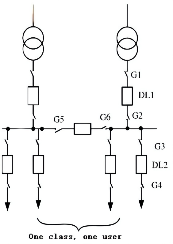
Fig. 2 Sectional Wiring of Single Bus
When a circuit breaker is installed in the middle of the bus, the bus is divided into two sections, so that important users can be powered by
two lines connected to the two sections of bus. When any section of bus fails, all important users will not be cut off. In addition, the two bus
sections can be cleaned and overhauled separately, which can reduce power failure to users.
Because the single bus sectional wiring not only retains the advantages of the single bus wiring itself, such as simplicity, economy and
convenience, but also serves its disadvantages to a certain extent, and the operation flexibility is improved (it can operate in parallel or in
separate columns), this wiring mode has been widely used.
However, the sectionalized wiring of single bus also has a significant disadvantage, that is, when a bus section or any bus disconnector fails
or is overhauled, all leads connected to the bus shall be powered off for a long time during the overhaul. Obviously, this is not allowed for
large capacity power plants and hub substations.
Scope of application of single bus sectional wiring: applicable to 6~10kV wiring of small and medium-sized power plants and 6~220kV substations.
3、 Single bus with bypass bus connection
Single bus with bypass bus connection is shown in Figure 3.
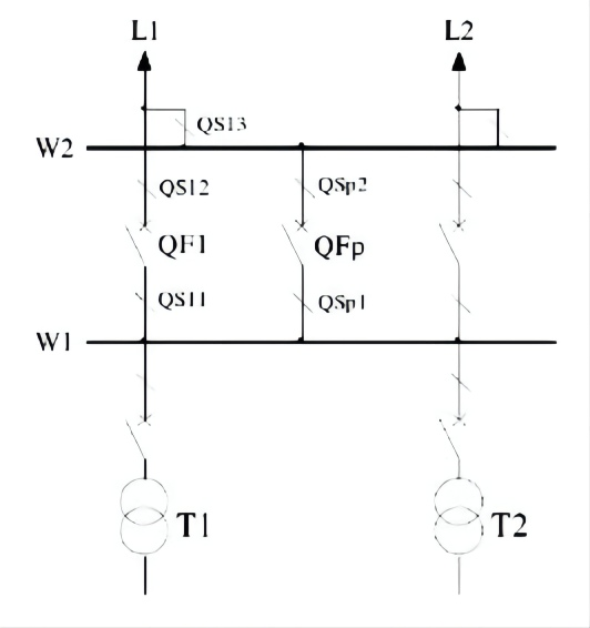
Fig. 3 Single bus with bypass bus
Function of bypass bus: maintenance of any incoming and outgoing circuit breakers can be carried out without power failure.
Steps for uninterrupted maintenance of circuit breaker QF1:
1) Use bypass circuit breaker QF0 to charge bypass bus W2, close QSp1 and QSp2, and then close GFp.
2) After successful charging, make outgoing circuit breaker QF1 and bypass circuit breaker QF0 operate in parallel and close QS13.
3) Exit circuit breaker QF19 and pull QF1, QS12 and QS11.
4) Hang ground wire (or grounding knife) on both sides of QF1 for maintenance.
Principles for erection of bypass bus:
1) 10kV lines are generally not erected because important users are powered by dual power supplies; The price of 10kV circuit
breaker is low, and special standby circuit breaker and handcart circuit breaker can be set.
2) 35kV lines are generally not erected for the same reasons, but the following conditions can also be considered: when there are
many outgoing circuits (more than 8); There are more important users and single power supply.
3) When there are many outgoing lines of 110kV and above lines, they are generally erected because of the long maintenance time
of the circuit breaker (5-7 days); The influence scope of line outage is large.
4) The bypass bus is not installed in small and medium-sized hydropower plants because the maintenance of the circuit breaker is
arranged in the bitter water season.
4、 Double bus connection
The double bus connection mode is proposed for the shortcomings of single bus sectional connection. Its basic connection mode is
shown in Figure 4, that is, in addition to the working bus 1, a group of standby bus 2 is added.
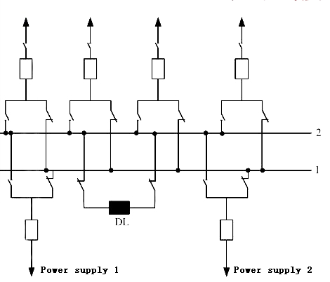
Fig. 4 Double bus connection
Since there are two groups of buses, they can be used as standby for each other. The two groups of buses are connected by bus tie
circuit breaker DL, and each circuit is connected to the two groups of buses through a circuit breaker and two disconnectors.
During operation, the disconnector connected to the working bus is connected and the disconnector connected to the standby bus
is disconnected.
Features of double bus connection:
1) Take turns to repair the bus without interrupting the power supply. When repairing the bus disconnector of any circuit, only
disconnect the circuit.
2) When the working bus fails, all circuits can be transferred to the standby bus, so that the device can quickly restore power supply.
3) When repairing the circuit breaker of any circuit, the power supply of the circuit will not be interrupted for a long time.
4) When the circuit breaker of individual circuit needs to be tested separately, the circuit can be separated and connected to the
standby bus separately.
The most important operation of double bus connection is to switch the bus. The following illustrates the operation steps by taking the
maintenance of working bus and outgoing circuit breaker as an example.
(1) Maintenance work bus
To repair the working bus, all power supplies and lines must be switched to the standby bus. To this end, first check whether the standby
bus is in good condition. The method is to connect the bus tie breaker DL to make the standby bus live. If the standby bus has poor
insulation or fault, the circuit breaker will automatically disconnect under the action of relay protection device; When there is no fault in
the spare bus, the DL will remain connected. At this time, since the two groups of buses are equipotential, all disconnectors on the standby
bus can be connected first, and then all disconnectors on the working bus can be disconnected, so that the bus transfer is completed. Finally,
the bus tie breaker DL and the disconnector between it and the working bus must be disconnected. So as to isolate them for maintenance.
(2) Repair the circuit breaker on one outgoing line
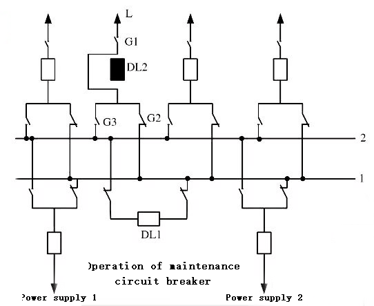
Fig. 5 Double bus maintenance circuit breaker
When overhauling the circuit breaker on any outgoing line without expecting the line to be powered off for a long time, for example,
when overhauling the circuit breaker on outgoing line L in Figure 5, first use the bus tie breaker DL1 to test that the standby bus is in
good condition, that is, disconnect DL1, then disconnect DL2 and disconnectors G1 and G2 on both sides, then disconnect the lead
connector of circuit breaker DL2, replace circuit breaker DL2 with a temporary jumper, and then connect the disconnector G3
connected to the standby bus, Then close the line side disconnector G1, and finally close the bus tie breaker DL1, so that line L is put
into operation again. At this time, the bus tie circuit breaker replaces the function of the circuit breaker, so that Line L can continue
to supply power.
To sum up, the main advantage of double bus is that the bus system can be overhauled without affecting the power supply. However,
double bus connection has the following disadvantages:
1) The wiring is complex. In order to give full play to the advantages of double bus connection, a lot of switching operations must be
carried out, especially when the disconnector is regarded as an operating electrical appliance, which is easy to cause major accidents
due to misoperation.
2) When the working bus fails, the power will be cut off for a short time during bus switching. Although the bus tie circuit breaker can
be used to replace the circuit breaker during maintenance, a short time power outage is still required during the installation and
connection of jumper bars, which is not allowed for important users.
3) The number of bus disconnectors is greatly increased compared with single bus connection, thus increasing the floor area of power
distribution equipment and investment.
5、 Connection of double bus with bypass bus
In order to avoid short-time power failure during maintenance of circuit breaker, double bus with bypass bus can be used, as shown
in Figure 6.
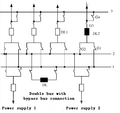
Fig. 6 Double bus with bypass bus connection
Bus 3 in Figure 6 is the bypass bus, and circuit breaker DL1 is the circuit breaker connected to the bypass bus. It is in the off position
during normal operation. When it is necessary to repair any circuit breaker, DL1 can be used instead of causing power failure. For example,
when circuit breaker DL2 on line L needs to be overhauled, circuit breaker DL1 can be closed to energize bypass bus, then bypass bus
disconnector G4 can be closed, finally circuit breaker DL2 can be disconnected, and then disconnectors G1, G2, G3 can be disconnected
to overhaul DL2.
In the single bus and double bus connection described above, the number of circuit breakers is generally greater than the number of
connected circuits. Due to the high price of high-voltage circuit breakers, the required installation area is also large, especially when
the voltage level is higher, this situation is more obvious. Therefore, the number of circuit breakers shall be reduced as far as possible
from the economic point of view. When there are few outgoing lines, the bridge connection without bus can be considered.
When there are only two transformers and two transmission lines in the circuit, fewer circuit breakers are required for bridge connection.
Bridge connection can be divided into “internal bridge type” and “external bridge type”.
(1) Inner bridge connection
The wiring diagram of internal bridge connection is shown in Figure 7.
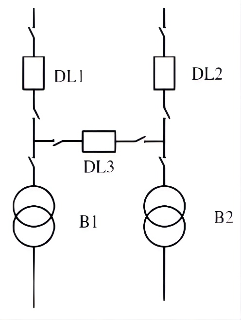
Figure 7 Inner Bridge Wiring
The characteristic of internal bridge connection is that two circuit breakers DL1 and DL2 are connected to the line, so it is convenient to
disconnect and input the line. When the line fails, only the circuit breaker of the line will be disconnected, while the other circuit and two
transformers can continue to work. Therefore, when one transformer fails, the two circuit breakers connected to the transformer will be
disconnected, so that the relevant lines will be out of service for a short time. Therefore, this limit is generally applicable to long lines and
transformers that do not require frequent switching.
(2) External bridge connection
The wiring diagram of overseas Chinese wiring is shown in Figure 8.
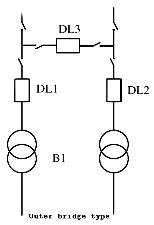
Fig. 8 External Bridge Wiring
The characteristics of external bridge connection are opposite to that of internal bridge connection. When the transformer fails or needs
to be disconnected during operation, only circuit breakers DL1 and DL2 need to be disconnected without affecting the operation of the line.
However, when the line fails, it will affect the operation of the transformer. Therefore, this kind of connection is suitable for the case where
the line is short and the transformer needs to be switched frequently. Generally, it is widely used in step-down substations.
In general, the reliability of bridge connection is not very high, and sometimes it is necessary to use disconnectors as operating appliances.
However, due to the few appliances used, simple layout and low cost, it is still used in 35~220kV distribution devices. In addition, as long
as appropriate measures are taken for the layout of power distribution devices, this kind of connection may develop into single bus or double
bus, so it can be used as a transition connection at the initial stage of the project.
Post time: Oct-24-2022